| STEP |
IMAGE |
DESCRIPTION
|
| 1 |
 |
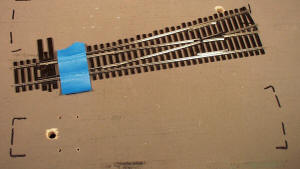
#1 Center point rails with masking tape. Place switch on layout and mark position with marking pen so it can be returned to its same position. Using a pin vise and small drill, drill down into top of layout thru tie bar as shown. This will create a guide hole to drill the 5/16" hole completely through layout. |
| 2 |
 |
#2 Remove switch and drill 1/8” starter hole, then 5/16” finish hole, or drill 3/8” finish hole if layout is thicker than 1 1/2”. |
| 3 |
 |
#3 Chamfer both top and bottom of hole. |
| 4 |
|
#4 This is the drill template shown in our instruction sheet. It is a must that you use this template and make a drill fixture. Using the drill fixture will exactly locate the four mounting holes in relation to the 5/16”. This means that the Blue Point is centered every time you mount it so you can achieve equal tension on the switch point to stock rail tension. From our instruction you can make your own drill fixture or buy one from us.
Buy Drill Fixture - # 40010 - Drill Template
|
| 5 |
 |
#5 Place the drill template in 5/16” hole. Make sure centerline of fixture is aligned with centerline of track. Now drill the four holes completely through the layout. |
| 6 |
 |
#6 This picture shows drilled 5/16” hole, mounting holes and switch relocation marks |
| 7 |
 |
#7 Shows chamfered 5/16" hole and marked mounting holes. By marking mounting holes with black marking pen makes them easier to find when attaching Blue Point under layout. A minimum of two screws mounted diagonally will hold the Blue Point fine. |
| 7a |
 |
#7a Complete “Flex Link Starter Kit” (#40022) for mounting and operating one Blue Point. |
| 8 |
 |
#8 Pre assemble Blue Point, wire, clevis and bracket with black clamp. |
| 9 |
 |
#9 Picture shows Flex Link clamp and screw. Flex Link clamp has two hole sizes, one small and one large. Screw should pass through large hole and screw into small hole. When Blue Point, bracket and clamp are mounted under layout screw head should face toward floor so it can be adjusted easily. |
| 10 |
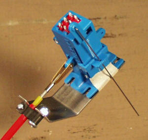 |
#10 Complete Blue Point and Flex Link parts assembled ready to mount to layout. We used masking tape to hold bracket to Blue Point for easier installation. We have used two screws mounted diagonally across from each other with good success. Feed Blue Point control wire up through hole in layout and into throw bar hole in switch points. Then we first install one screw and snug it up, but not completely tight. This holds Blue Point in place so second screw can be installed easily. Trim masking tape off of each side of Blue Point so it will move when final adjustments are made. |
| 11 |
 |
#11 Complete Blue Point assembly mounting with red outer tube sticking through 11/64” hole that has been drilled through back-up block. Remove yellow tube before going to next step. |
| 11A |
 |
#11A & B By plucking the switch points like a guitar to check point tension you can get an idea of which way to slide the Blue Point machine. Moving in either direction will put more or less tension on the point rails against the stock (outside) rails. The objective is to have equal pressure against the outside rails. Once you have adjusted a couple of Blue Points you will get the hang of it very quickly.
|
| 11B |
 |
| 12 |
 |
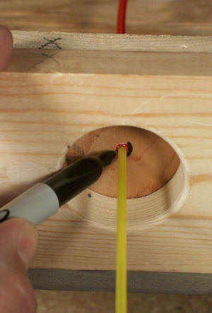
#12 Mark red tube at face of back-up block |
| 13 |
 |
#13 Push red tube out and cut at marked line. Be careful not to split tubing at end when trimming off. |
| 14 |
 |
#14 Push red tube back into back-up block until it is flush. |
| 15 |
 |
#15 Install threaded rod into yellow tube about a 1/4” deep. Grab stud with needle nose pliers just above the 1/4” area so balance of threads will not be damaged. This will prevent problems when threading stud into clevis. |
| 16 |
 |
#16 Push yellow tube into red tube and screw into clevis on Blue Point. Operate the Blue Point by pushing and pulling yellow tube. Make sure action feels smooth, with no binding. Now push yellow tube in and mark it with black pen. |
| 17 |
 |
#17 Unscrew yellow tube from clevis and pull out slightly, enough to trim tubing off at mark. Now attach control knob with 2-56 screw and washer to yellow tube. Make sure it is tight. Then screw threaded stud back into clevis. This step might be made easier by using the Philip head screw in the control knob to screw the stud back into clevis. When knob is pushed in there should be a slight space between back of knob and the face of the back-up block. |
| 19 |
 |
#19 Picture shows recessed or flush mounted control knob mounting. |
| 19A |
 |
#19a After Blue Point is completely mounted grab the control wire with your fingers and gently pull up on it while you are cutting it off. Try to keep your cutters as flush to the ties as you can as shown in the picture, this will leave very little sticking up so it will not interfere with track cleaning. |


